01 / MOULD
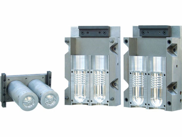
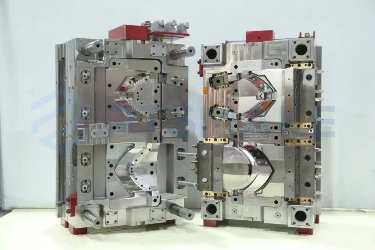
Blow Mould Design
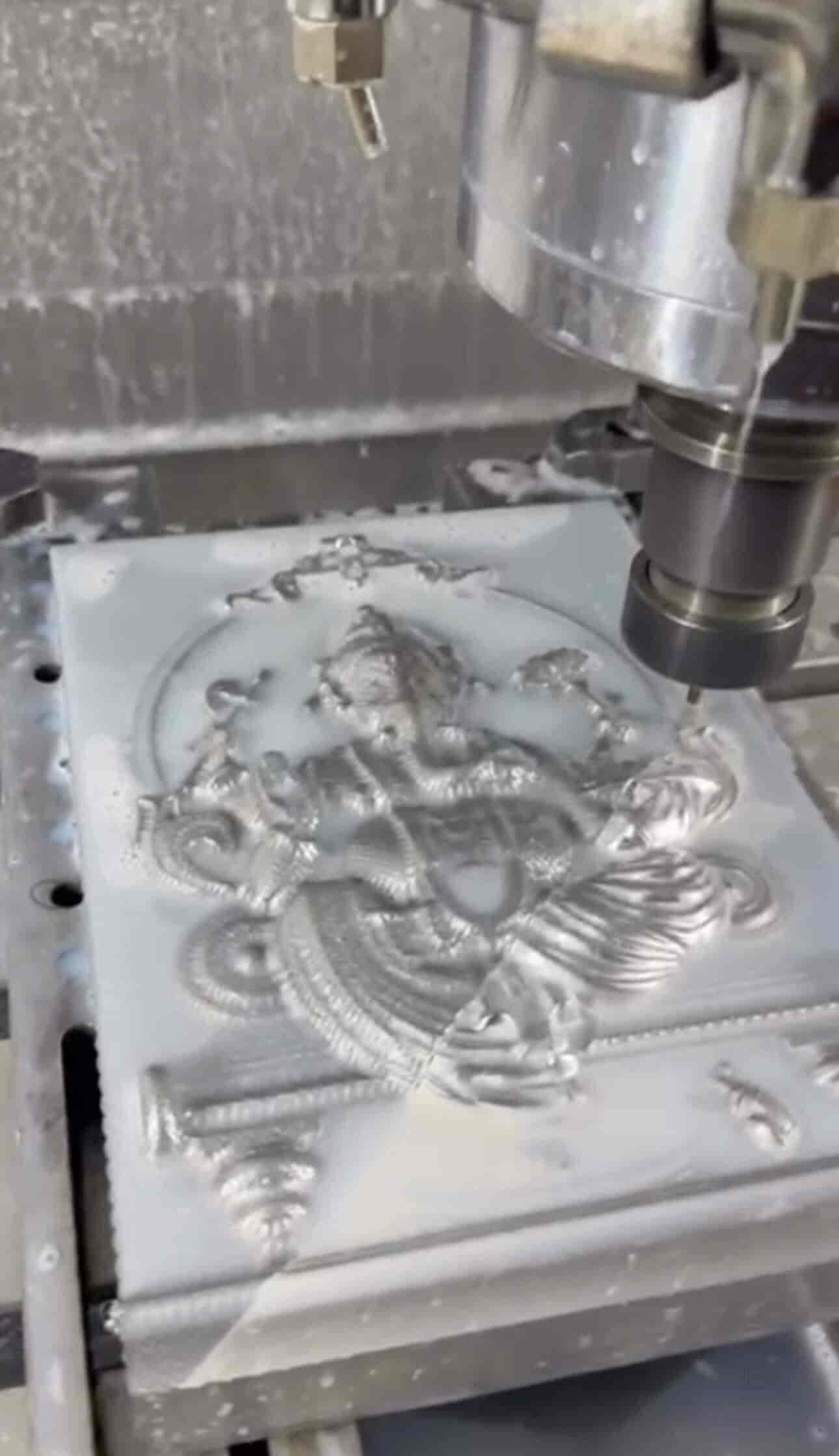
Blow mould design, toolpath and machining support.
Professional CNC programming and CAD/CAM support for toolrooms, machine shops and mould manufacturers.
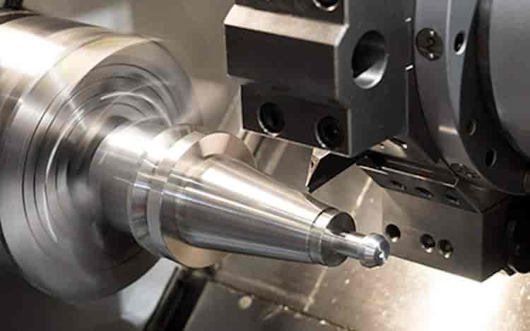
Open the browser-based CNC Code Lab directly from the Home page. Upload a 2D turning DXF, work in X diameter/radius mode, generate turning code, verify it and watch the X/Z toolpath simulation.




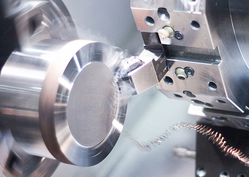
CNCVEYRA provides practical remote CNC programming and CAD/CAM support for toolrooms, mould manufacturers, machine shops and engineering companies worldwide.
From part design and physical-part understanding to toolpath generation, mould modification and CNC programming, our work is focused on what can actually be manufactured.
Blow mould • Toolpath • CAM
Understand the component and manufacturing requirement.
Build or modify the engineering model.
Develop machining strategies in CAM.
Prepare the program for the target machine.
Blow mould design, toolpath and machining support.
Engineering development and modification from part requirements.
3-axis machining strategies and CNC program support.
Send the job details. The form will build your WhatsApp message automatically—no retyping.
Drawing / 3D file: attach it directly in WhatsApp after the message opens.
We are interested in experienced CNC Programmers, CAD/CAM Engineers and manufacturing professionals.
After WhatsApp opens, attach your CV/PDF and send the application.
A growing technical library for CNC programmers, machinists, toolrooms and CAD/CAM professionals. Select an article to open the complete long-form guide.
Learn how to calculate spindle speed, feed rate, chip load and feed per tooth for CNC milling, with practical VMC examples and common programming mistakes.
A practical explanation of MRR in CNC milling, including the formula, units, roughing examples and how MRR relates to productivity and spindle load.
Understand flank wear, crater wear, chipping, built-up edge and heat-related tool failure, with practical methods for extending CNC milling tool life.
A detailed CNC milling guide to chatter, vibration, resonance, tool overhang, spindle speed selection and practical methods for achieving stable cuts.
Learn how CNC work offsets G54–G59 work, how machine coordinates differ from work coordinates, and how to set and verify offsets safely.
Understand the difference between G90 absolute and G91 incremental programming, with examples, risks and practical VMC programming advice.
A practical guide to G00 rapid positioning and G01 linear interpolation, including safe moves, feed control and common programming mistakes.
Learn how G02 clockwise and G03 counterclockwise circular interpolation work, including I/J/R programming, arc direction and troubleshooting.
Understand cutter radius compensation G40, G41 and G42, how wear offsets work and why compensation errors occur in CNC milling.
A detailed guide to CNC tool length compensation, G43, H registers, tool length measurement and safe Z-axis programming on VMC machines.
Learn the purpose and differences of common drilling canned cycles G81, G82 and G83, including peck drilling, dwell and safe retract considerations.
Understand the practical difference between 3-axis and 3+2 CNC machining, including rotary positioning, work offsets, tool orientation and machining strategy.
A practical comparison of CNC roughing and finishing operations, including stock allowance, stepdown, stepover, tool selection and surface-quality considerations.
Learn the difference between climb and conventional milling, cutting-force direction, surface finish, machine backlash and practical toolpath selection.
Understand CNC surface finish factors including Ra, cusp height, tool diameter, stepover, feed and finishing toolpath selection for 3D machining.
Learn how to estimate spindle speed and feed for CNC drilling using cutting speed and feed per revolution, with practical examples and safety considerations.
A practical CNC milling guide for aluminium covering tool geometry, spindle speed, chip load, coolant, flute count and chip evacuation.
Learn the main factors affecting CNC milling of steel, including cutting speed, chip load, tool coating, engagement, coolant and machine rigidity.
A complete overview of the CNC mould and die machining workflow, from CAD preparation and stock setup to roughing, rest machining, finishing and NC verification.
Understand CNC postprocessors, why CAM toolpaths cannot simply be sent directly to every machine, and how postprocessor errors can affect G-code.
A practical pre-machining checklist for verifying CNC programs, including coordinates, offsets, tool data, rapid moves, collisions and simulation.
Understand cutter deflection in CNC milling, the effect of tool diameter and overhang, and practical methods for improving dimensional accuracy.
Learn the fundamentals of CNC workholding and fixture planning, including locating, clamping, rigidity, accessibility and collision avoidance.
A detailed introduction to CNC G-code structure, modal commands, program start, tool calls, work offsets, motion, spindle, coolant and program end.
Learn common CNC M-codes used in VMC programming, including spindle commands, coolant, program stop and program end, with controller-specific cautions.
Understand chip load and feed per tooth in CNC milling, how flute count changes feed rate, and why feed must be balanced with spindle speed.
Cutting speed tells you how fast the cutting edge travels through the material, while feed rate tells you how quickly the tool advances through the work. These two values must be selected together; choosing one without considering the other can produce rubbing, chatter, excessive heat or premature tool wear. For milling, the basic relationship is spindle speed N = (1000 × Vc) / (π × D), where Vc is cutting speed in m/min and D is cutter diameter in mm. Once RPM is known, table feed can be calculated as F = fz × z × N, where fz is feed per tooth in mm/tooth and z is the number of effective teeth.
For example, consider a 10 mm, 4-flute carbide end mill cutting a steel component. If the selected cutting speed is 120 m/min, RPM is approximately 3819. If the starting chip load is 0.04 mm/tooth, feed becomes 0.04 × 4 × 3819 ≈ 611 mm/min. These are starting values, not universal settings. Tool coating, workpiece hardness, radial engagement, axial depth, coolant, machine rigidity and holder runout can all require adjustment.
A useful practical method is to calculate RPM first, then calculate feed from chip load. If the tool is rubbing instead of cutting, simply reducing feed can make the problem worse. Conversely, increasing feed without checking spindle load can overload the tool. In finishing, the programmed feed may be reduced because engagement and surface-quality requirements are different. CAM software often allows feed and speed changes by operation, which is useful for roughing, semi-finishing and finishing.
Always check the machine maximum RPM and the cutter manufacturer's recommended range. On a rigid VMC, stable chip formation is usually a better indicator than blindly following a single number. Watch spindle load, sound, chips and surface finish after a controlled test cut. Different work materials require different starting values, so a shop should maintain its own proven cutting-data library.
The key takeaway is simple: calculate RPM from cutting speed and tool diameter, then calculate feed from chip load, flute count and RPM. Treat the result as a controlled starting point and adjust it according to tool engagement, material, machine rigidity and manufacturer recommendations.
Material Removal Rate, commonly written as MRR, describes how much material a cutting process removes per unit of time. In milling, a simple volumetric approximation is MRR = width of cut × depth of cut × feed rate. If width and depth are in millimetres and feed is in mm/min, the result is mm³/min. Dividing by 1000 converts mm³/min to cm³/min. MRR is particularly useful when comparing roughing strategies because it connects tool engagement and feed directly to productivity.
Suppose a cutter removes a 20 mm radial width at a 3 mm axial depth while feeding at 800 mm/min. The basic calculation is 20 × 3 × 800 = 48,000 mm³/min, or 48 cm³/min. This is a geometric removal rate. The actual achievable rate may be lower because of machine power, spindle torque, tool strength, workholding, vibration and the changing engagement of the cutter.
MRR is valuable during roughing because a high feed alone does not guarantee high productivity. A small cutter taking a tiny width may travel very fast but still remove little material. A larger cutter with controlled engagement can sometimes remove more material at a lower programmed feed. High-efficiency milling strategies deliberately control radial engagement so that the cutter maintains a more predictable load.
When comparing operations, record the cutter diameter, number of flutes, RPM, feed, axial depth and radial engagement. Then monitor spindle load and tool condition. If load rises sharply at corners or deep pockets, the programmed MRR may not represent the true cutting difficulty. Adaptive or constant-engagement toolpaths can reduce these peaks and make the average removal rate more sustainable.
MRR should therefore be used as a planning metric, not as a target that must be maximised at any cost. A stable cut that removes material consistently is generally more useful than a very aggressive cut that breaks tools, damages holders or creates unacceptable vibration.
MRR provides a quick way to quantify roughing productivity: width × depth × feed. Use it alongside spindle power, tool engagement and machine rigidity rather than treating a high MRR as automatically better.
Tool life is the usable cutting time or production quantity a tool can achieve before it no longer meets the required dimensional, surface or process condition. In CNC milling, wear is influenced by cutting speed, feed, depth and width of cut, workpiece material, tool material and coating, coolant, machine rigidity and holder condition. Tool life is not simply a matter of how many parts a cutter can make; a tool can still cut while producing unacceptable size variation or surface finish.
Flank wear occurs on the relief face of the cutting edge and is one of the most common wear mechanisms. Crater wear develops on the rake face when the chip flow and temperature remove tool material. Edge chipping can occur when the cutting edge is overloaded, interrupted cuts are unstable or the tool is too brittle for the application. Built-up edge is common in some ductile materials and can change the effective geometry of the cutting edge, leading to poor finish and dimensional inconsistency.
Cutting speed has a strong effect on heat generation and therefore tool life. Increasing speed can improve productivity, but excessive speed can rapidly increase wear. Feed per tooth controls chip thickness and must be large enough to avoid rubbing. At the same time, an excessive feed or sudden engagement can chip the edge. This is why changing one parameter without considering the others often creates confusing results.
Practical tool-life improvement begins with repeatability. Use the same holder style, tool projection and coolant condition where possible. Check runout because an individual flute carrying much more load can fail early. Keep the workholding rigid and avoid unnecessary tool overhang. For roughing, use a stable engagement strategy rather than forcing the cutter into full-width cuts when the machine cannot support them.
For production work, establish a measured tool-change rule. Record parts per tool, cutting time, spindle load and finish quality. Replace tools before catastrophic failure when process consistency matters. A small amount of planned tool cost is often much cheaper than a broken tool, damaged workpiece or lost machine time.
Good tool life comes from balanced cutting conditions and repeatable setup. Monitor wear and process behaviour, control runout and engagement, and use measured tool-change limits instead of waiting for catastrophic failure.
Chatter is a self-excited vibration that can appear during machining as a repeating pattern on the workpiece, a harsh cutting sound, visible vibration or unstable spindle load. It is different from ordinary cutting noise. Chatter often leaves a regular surface pattern and can quickly damage a cutting edge. The root cause may involve the tool, holder, spindle, workholding, machine structure, workpiece geometry or cutting parameters.
Tool overhang is one of the first things to inspect. A long, slender tool behaves less rigidly than a short tool, so the same cutting force can produce much more deflection. If a deep cavity requires long reach, use the shortest practical tool and consider a larger diameter, reduced radial engagement or a suitable high-rigidity holder. Workpiece clamping should also be checked because a flexible plate can vibrate even when the machine and tool are rigid.
Cutting conditions can trigger resonance. If a stable operation becomes unstable after an RPM change, the new speed may be exciting a structural frequency. A practical shop approach is to make controlled changes rather than changing RPM, feed and depth simultaneously. Try reducing radial engagement, reducing axial depth, increasing or decreasing RPM within a safe range, or changing tool geometry. Feed should then be adjusted so chip load remains appropriate.
Full-slot milling can create high radial engagement and large instantaneous cutting forces. In pockets, a constant-engagement toolpath can reduce force variation. For finishing, a lighter radial cut with a suitable feed can improve surface quality. In some cases, changing flute count or using a variable-pitch cutter can interrupt the regular timing that sustains chatter.
Never treat chatter simply by slowing everything down. A very low feed can cause rubbing and heat, while an unsuitable RPM can keep the cutter in the unstable region. Diagnose the source, make one controlled change at a time and verify the result through sound, surface pattern and spindle-load behaviour.
Chatter is usually a rigidity and stability problem, not just a 'feed too high' problem. Reduce unnecessary overhang, control engagement, verify workholding and make controlled spindle-speed changes while maintaining a sensible chip load.
A CNC control needs a way to relate the programmed part coordinates to the actual location of the workpiece on the machine. Work coordinate systems provide that relationship. Common Fanuc-style controls use G54 through G59 as standard work offsets. The same basic concept exists across many controllers, although screen names, setting procedures and additional offset options can differ.
Machine coordinates are tied to the machine reference system, while the work coordinate system allows the programmer to define a practical part zero. For example, the top face of a fixture or a corner of a rectangular component can be assigned X0 Y0 Z0 in G54. When the program commands G54, subsequent coordinates are interpreted relative to that work offset until another coordinate system is selected.
Multiple offsets are useful when several parts are mounted on one fixture. G54 can represent the first component, G55 the second, and so on. The program geometry can remain identical while only the work offset changes. This is one reason fixture-based production can be highly efficient. However, every offset must be verified because an incorrect value can cause the machine to move to an unintended location.
Z zero deserves particular attention. Some shops set Z0 at the top of the finished part, while others use the fixture, stock top or a probing routine. The choice is a programming standard and must be documented. Tool length compensation and work offsets perform different jobs: the work offset establishes where the part coordinate system sits, while tool length compensation accounts for the individual tool's length.
Before running a new program, verify active work offset, tool number, tool length, spindle direction, safe Z position and the expected first movement. Use single block, dry run or graphics where available. Never assume that a G54 value is correct simply because the program ran previously on another setup.
G54–G59 are work coordinate systems used to map programmed part coordinates to actual fixture locations. A safe setup requires clear zero conventions and verification of both work offsets and tool length compensation.
Coordinate mode determines how the control interprets programmed positions. In common Fanuc-style programming, G90 selects absolute programming and G91 selects incremental programming. In absolute mode, a command such as X50 means move to the position X50 in the active work coordinate system. In incremental mode, X50 means move 50 mm from the current position.
Absolute programming is often easier to audit because every position can be compared directly with the drawing or model. For example, a sequence such as G90 G01 X20 Y20 followed by X80 Y20 describes known locations. Incremental programming can be useful for repetitive patterns because the same movement can be repeated from the current position. It is also common in certain canned-cycle or probing logic, depending on the controller and application.
The main risk is accidentally leaving the control in the wrong mode. If a programmer intends an absolute position but the machine is in G91, the resulting move can be completely different. For this reason, professional programs commonly establish important modal conditions explicitly near the beginning of the program. CAM posts also manage these modes according to the postprocessor's logic.
Consider a simple example. If the current position is X10 and the program commands G90 X50, the target is X50. If G91 is active and the same X50 command is issued, the target becomes X60. The numerical value is identical, but the meaning is different. This is why modal state is as important as the individual line being read.
When editing code manually, look at several lines before the point of change. Check G90/G91, active plane, units, work offset, cutter compensation and feed mode. Do not judge one line in isolation. On production machines, prove manually edited programs through simulation or controlled dry runs before cutting the component.
G90 defines positions from the active coordinate origin; G91 defines movements relative to the current position. Always confirm the active mode before editing or manually running CNC code.
G00 and G01 are among the most fundamental CNC motion commands. G00 is used for rapid positioning, while G01 commands a controlled linear move at the programmed feed rate. A rapid move is intended for positioning when the tool is not cutting. A linear interpolation move is used when the cutter needs to follow a controlled straight path through or along the workpiece.
A safe program separates positioning from cutting. For example, the tool may rapid to X50 Y20 at a safe Z height, then feed down to a cutting depth with G01, and finally feed along the machining path. The exact safe height depends on the setup, fixture, workpiece and machine. A rapid command should never be treated as a cutting move. If the tool is still near the material and a rapid move is commanded, the machine can move much faster than expected.
G01 normally requires a feed value unless the control is already operating under a valid modal feed. The feed is interpreted according to the active feed mode and controller settings. In milling, the programmer must also consider whether the feed is appropriate for the cutter diameter, flute count, material and engagement. A rapid move has a different purpose and should not be used to control cutting speed.
When reading G-code, pay attention to modal behaviour. Once G01 is active, subsequent coordinate blocks may continue as linear feed moves until another motion mode is selected. Similarly, G00 can remain active. This is why safe program structure and explicit transitions matter.
A common manual-programming mistake is combining a deep Z movement and a long XY rapid in one block without confirming the current position. Another is assuming that the machine will automatically protect the tool from clamps. It will not. Clearance must be programmed and verified from the actual setup.
G00 is for rapid positioning and G01 is for controlled linear cutting movement. Keep rapid moves at verified clearance, use sensible feed values for cutting, and remember that both commands are modal.
Circular interpolation allows a CNC machine to move along an arc instead of a straight line. In common milling code, G02 commands clockwise interpolation and G03 commands counterclockwise interpolation when viewed according to the active plane convention. For the standard XY plane, the programmer can define an arc using endpoint coordinates plus centre information such as I and J, or by using an R radius value depending on the controller and application.
I and J normally describe the incremental distance from the arc start point to the arc centre in the X and Y directions. This method gives the control explicit centre information and is widely used by CAM posts. R programming specifies a radius, but it can be ambiguous for certain arc geometries because the same endpoints and radius can correspond to different arc paths. Controller rules determine how the ambiguity is resolved.
For example, a program may move to the start point, activate G02, then command an endpoint with suitable I and J values. The control calculates the intermediate positions required to maintain the arc. The active plane matters: G17 is normally XY, G18 is XZ and G19 is YZ on many Fanuc-style controls. Therefore, the meaning of arc parameters changes with the selected plane.
Arc errors can occur when the programmed endpoint and centre information do not describe a valid circle within the control's tolerance. Manual editing is especially risky because a small coordinate error can make an arc invalid. CAM software reduces many of these mistakes, but the programmer still needs to understand what the postprocessor is outputting.
For manual verification, plot the start point, endpoint and centre. Confirm direction, radius and plane. Also check whether cutter compensation is active because the tool centreline path and finished geometry are related but not identical. This basic geometric check can prevent many unexpected arc moves.
G02/G03 create circular motion. Use the correct plane, direction and centre/radius definition, and verify the geometry rather than assuming an edited arc line is valid.
Cutter compensation allows the programmed path to represent the intended component geometry while the control offsets the tool centreline according to the cutter radius. In common Fanuc-style milling, G41 selects cutter compensation left, G42 selects compensation right, and G40 cancels it. The meaning of left or right depends on the direction of travel along the programmed path.
This feature is useful for controlling size without reposting an entire toolpath. For example, a finish contour can be programmed around nominal geometry and a small wear correction can be entered at the control. The machine then adjusts the tool centreline. This is particularly valuable in production when a measured feature is slightly over or undersize.
Compensation must be activated and cancelled in suitable lead-in and lead-out moves. A sudden activation on a line with insufficient movement can cause a compensation alarm or an unexpected path. The lead-in should provide enough room for the tool to establish the compensated position safely. The same principle applies when cancelling compensation at the end of a contour.
One important distinction is between geometry/radius compensation and wear compensation. Shops may use different offset conventions, but the underlying objective is to make small controlled corrections while maintaining a stable program. The actual offset register and sign behaviour depend on the controller and setup standard, so the machine manual and shop practice should be followed.
When troubleshooting, first confirm tool diameter or radius data, active compensation side, contour direction and lead-in geometry. A common mistake is changing the offset sign without understanding which side the control is applying. Use graphics or simulation where available and prove a new compensation strategy carefully.
G41/G42 shift the tool centreline relative to the programmed contour, while G40 cancels compensation. Correct direction, lead-in/lead-out geometry and offset conventions are essential.
Tool length compensation allows a CNC control to account for the physical length of each cutting tool. On many Fanuc-style milling controls, G43 is used to apply positive tool length compensation together with an H offset number. The H register contains the measured tool length value according to the machine's offset convention. This lets the same programmed Z coordinates be used with tools of different lengths.
Without reliable tool length compensation, a program cannot safely treat multiple tools as having the same physical tip position. Tool 1 may be short while Tool 5 is long, but both can be referenced to the same workpiece Z0 when their corresponding length offsets are correctly measured. The control combines the work coordinate system and tool length compensation to calculate the machine movement required to place the tool tip at the programmed location.
A typical tool-change sequence may call a tool, start the spindle, move to a safe location and then apply G43 H01 before entering the machining region. The exact order and safe moves depend on the machine and postprocessor. Some controls or shop standards use different conventions, so the actual machine documentation must be followed.
Tool measurement can be performed offline, with a tool presetter, or directly on the machine. Whatever method is used, the measurement must be repeatable. A wrong H value can cause a large Z error even when the G-code itself is correct. Before cutting, verify the active tool, H number and measured length. Single-block and dry-run procedures are useful when proving unfamiliar programs.
Tool length compensation is separate from the work offset. The work offset defines the part coordinate origin; tool length compensation accounts for the physical tool length. Understanding this separation makes G-code much easier to troubleshoot.
G43 H compensation connects the programmed Z position to the actual tool length. Always verify the correct H register and measurement before machining, and remember that tool length and work offsets perform different jobs.
Canned cycles reduce repetitive drilling code by allowing the control to perform a standard sequence from a compact command. G81 is commonly used for a basic drilling cycle, G82 adds a dwell at the bottom, and G83 is commonly used for peck drilling. Exact behaviour and available parameters vary by controller, so the machine manual and postprocessor should always take priority.
A basic drilling cycle typically defines a target Z depth, a retract or clearance plane and a feed rate. The machine positions to the hole location and executes the drilling sequence. With G81, the tool usually feeds to depth and retracts. G82 adds a dwell, which can be useful when bottom condition or chip clearing requires a pause. G83 breaks the drilling depth into pecks, retracting between steps to help evacuate chips and control heat.
Peck drilling is particularly useful for deeper holes where chips can accumulate in the flute and coolant cannot easily reach the cutting zone. Peck depth should be selected according to tool diameter, material, hole depth, coolant and tool manufacturer recommendations. Too large a peck can overload the tool, while an excessively small peck increases cycle time and can create unnecessary repeated entry into the hole.
Before using a canned cycle, confirm the initial point, R plane, final Z, feed, spindle direction and return behaviour. Some controls use parameters that change whether the tool returns to the initial plane or only the R plane. If the machine is configured differently from the postprocessor assumptions, the result can be unsafe.
For production, canned cycles make programs shorter and easier to maintain, but the programmer still needs to understand the underlying motion. Simulate the cycle and check nearby clamps or fixtures. A compact G83 line can still command substantial Z-axis movement.
G81 is a basic drilling cycle, G82 adds dwell, and G83 performs peck drilling. The exact syntax varies by controller, so verify cycle parameters and retract behaviour on the machine before running.
Three-axis machining controls X, Y and Z simultaneously while the cutting tool remains oriented along a fixed machine direction. 3+2 machining adds two rotary axes or an equivalent positioning system so the tool can be tilted and indexed to a new orientation before cutting. The rotary axes normally reposition and then remain fixed during a 3-axis cutting operation, although the exact machine architecture can vary.
The major benefit of 3+2 is improved access to angled faces and deep features. Instead of using a very long tool to reach an inclined wall, the machine can tilt the tool toward the surface. This can reduce tool overhang, improve rigidity and sometimes improve surface finish. It can also reduce the number of setups because multiple faces may be machined from one fixture.
Programming becomes more complex because tool orientation, rotary-axis limits, pivot behaviour, work offsets and postprocessor configuration become important. A CAM system must understand the machine's kinematics. The same toolpath can produce different machine movements on different machines, so the postprocessor is not a minor detail; it is part of the manufacturing system.
A good 3+2 workflow begins with defining the part coordinate system and selecting a safe tool axis. The CAM system then calculates the toolpath in the appropriate orientation. Before machining, verify rotary clearance, holder collision, spindle head clearance and the final machine positions. The machine may have cable, fixture or travel limitations that are not obvious from the CAD model alone.
3+2 does not automatically mean faster. It is valuable when the new orientation solves an access, rigidity or setup problem. For simple planar parts, standard 3-axis machining may remain more efficient. The best strategy is the one that provides stable cutting, acceptable accuracy and a practical setup.
3+2 machining uses rotary positioning to present the tool at different angles, then performs the cutting with the tool orientation fixed. It can improve access and rigidity, but requires a correct machine-aware postprocessor and collision verification.
Roughing and finishing have different objectives. Roughing removes material quickly while protecting the machine and tool from excessive load. Finishing focuses on achieving final dimensions, surface quality and edge definition. Trying to make one operation perform both jobs often leads to inefficient cutting conditions or inconsistent finish.
During roughing, the programmer normally leaves a controlled amount of stock for later operations. The roughing tool can use a geometry and cutting strategy designed for material removal, while the finishing tool follows a more precise path. The stock allowance must be large enough to ensure the finishing tool has material to cut, but not so large that finishing becomes unnecessarily heavy.
Stepdown describes axial depth per pass and stepover describes radial or lateral spacing between adjacent passes. Their correct values depend on tool diameter, material, tool geometry, machine rigidity and cutting strategy. A large stepdown can be efficient when axial cutting is stable, but deep engagement may increase deflection or heat. Similarly, a large stepover can increase material removal but also increase radial load.
Finishing often uses smaller radial engagement and a tool chosen for surface requirements. Ball nose tools are common for 3D surfaces, while flat end mills can be effective for planar features and some wall finishing. Surface finish also depends on cusp height, tool diameter, step-over, feed, tool runout and machine motion quality. A small stepover is not always the only answer; the tool geometry and cutting direction matter too.
A strong CAM strategy separates operations logically: rough the bulk stock, rest-machine inaccessible regions, semi-finish where useful, then finish walls, floors and 3D surfaces. This gives each toolpath a clear purpose and makes troubleshooting easier.
Roughing is about controlled material removal; finishing is about final geometry and surface quality. Leave predictable stock, choose tools for each job and use stepdown/stepover according to the actual cutting conditions.
Climb milling and conventional milling describe the relationship between cutter rotation and the direction of feed at the point of contact. In climb milling, chip thickness generally starts larger and decreases toward the exit. In conventional milling, the chip starts thin and increases toward the exit. The difference changes cutting force direction, tool behaviour and surface quality.
On modern rigid CNC machines with appropriate tooling and workholding, climb milling is commonly preferred for many finishing and general milling operations because it can provide favourable chip formation and surface finish. However, the machine must be capable of handling the resulting cutting-force direction. Older or mechanically worn machines with significant backlash require additional caution because cutter forces can pull the table or work into the cut.
Chip thickness is important. In climb milling, the cutter enters with maximum chip thickness and exits near zero. This can reduce rubbing and help the edge cut cleanly. In conventional milling, the edge initially rubs against a thin chip before the chip becomes thicker. The exact effect depends on cutter geometry, material and engagement.
Toolpath direction also affects burr formation and edge condition. For mould and die work, the programmer may select direction based on wall quality, tool deflection and the geometry of the feature. A finishing pass can be designed so cutting forces push the tool away from or toward a critical wall depending on the required accuracy.
There is no universal rule that ignores setup conditions. Check the machine's rigidity, backlash, workholding and cutter manufacturer's recommendations. For a new setup, simulate the toolpath and inspect the actual engagement rather than relying only on the label 'climb' or 'conventional.'
Climb milling and conventional milling differ in cutter/feed relationship and chip formation. Climb milling is often preferred on rigid CNC machines, but machine condition, workholding and cutter engagement must always be considered.
Surface finish in CNC machining is influenced by cutting conditions, tool geometry, machine motion, material and the toolpath itself. Ra is a common roughness parameter, but a drawing may specify another roughness value or a particular visual finish. A programmed surface can look smooth while still having measurable scallops, or a measured roughness can be acceptable while the toolpath leaves visible marks in certain lighting.
For 3D machining with a ball nose cutter, stepover has a direct relationship with cusp height. When adjacent passes are separated too far, the remaining material between them becomes more pronounced. Reducing stepover generally reduces cusp height, but it also increases machining time. Tool diameter and surface curvature also matter, so the same stepover percentage does not produce identical results on every geometry.
Feed rate and spindle speed affect the cutting edge's interaction with the material. Tool runout can cause one flute to carry more load, creating uneven marks. Tool overhang and machine vibration can amplify the pattern. On mould surfaces, a poor finishing strategy may produce visible toolpath lines even when the nominal CAD geometry is correct.
Finishing strategy should be chosen according to geometry. Parallel passes may work well on some open surfaces, while constant scallop or contour-based strategies can maintain more consistent surface quality on complex shapes. Steep and shallow regions may benefit from separate operations. A smaller ball nose is not automatically better; it may require many more passes and can be more sensitive to deflection.
A practical approach is to define the required finish first, then select tool diameter, stepover, feed and toolpath. Verify the result with measurement where the drawing requires a numerical roughness value. Visual inspection alone should not be used as a substitute for a specified measurement method.
Surface finish is a system result, not just a stepover setting. Tool geometry, cusp height, feed, runout, rigidity and the chosen finishing strategy all influence the final surface.
Drilling calculations are usually based on cutting speed and feed per revolution. A common relationship for spindle speed is N = (1000 × Vc) / (π × D), where Vc is cutting speed in m/min and D is drill diameter in mm. Feed rate can then be calculated as F = f × N, where f is feed per revolution in mm/rev. These formulas provide a starting point, but drill geometry, work material, hole depth, coolant and manufacturer data must be considered.
For example, if a 10 mm drill is used at a cutting speed of 25 m/min, the calculated spindle speed is approximately 796 RPM. If the recommended starting feed is 0.12 mm/rev, the feed rate is about 95.5 mm/min. The actual recommended values should come from the drill manufacturer or a proven shop cutting-data table for the specific material.
Deep-hole drilling creates additional challenges because chip evacuation becomes more difficult. A standard drill may not be suitable for a deep hole, and the cycle may require pecking or another drilling strategy. Coolant delivery and hole geometry also become important. Excessive pecking can increase cycle time and repeatedly load the cutting edge, while insufficient chip evacuation can cause packing and tool failure.
Drill point geometry changes cutting behaviour. Different materials may require different point angles, coatings and edge preparations. A drill that performs well in mild steel may require very different conditions in stainless steel or aluminium. Workholding and spindle alignment also matter because a misaligned setup can produce poor hole quality.
Always confirm the machine's spindle range and the drill's recommended operating window. After the first hole, inspect chips, burrs, sound and hole size. A controlled first-off check is much safer than assuming a formula alone guarantees a successful drilling operation.
Use cutting speed to estimate drill RPM and feed per revolution to calculate feed rate. Then adjust for drill geometry, material, hole depth, coolant and manufacturer recommendations.
Aluminium is generally machinable at high cutting speeds, but successful milling depends heavily on chip evacuation and avoiding built-up material on the cutting edge. Sharp carbide tools with geometry suited to aluminium are commonly used. Two- or three-flute tools can provide generous flute space for chip evacuation, although the correct choice depends on the operation and tool manufacturer's recommendations.
The same formulas used for other milling materials apply: RPM = (1000 × Vc)/(π × D), and feed = fz × z × RPM. Aluminium may support a higher cutting speed than many steels, but the correct value depends on alloy, tool coating, tool geometry, engagement and machine capability. High spindle speed without sufficient feed can cause rubbing and heat rather than efficient cutting.
Chip evacuation is especially important in pockets. If chips are recut, the tool can become hot and the surface may degrade. Air blast, flood coolant or suitable mist systems can help move chips away from the cutting zone, subject to the machine and shop's safety requirements. In deep pockets, toolpath strategy should also prevent chips from accumulating beneath the cutter.
Tool geometry can make a major difference. Sharp cutting edges, suitable rake and polished flute surfaces can reduce adhesion in aluminium. A tool with geometry designed for steel is not necessarily the best tool for high-speed aluminium work. Tool runout should also be checked because uneven flute loading can cause one edge to wear or accumulate material faster.
For finishing aluminium, a sharp tool and stable engagement can produce excellent surfaces. Avoid unnecessary dwell at the bottom of a pocket because stationary cutting can generate heat. Keep the setup rigid and monitor chips and surface finish during the first trial.
Aluminium rewards sharp tooling, efficient chip evacuation and a sensible chip load. Calculate RPM and feed from the tool data, then verify the actual cut rather than relying on speed alone.
Steel milling requires a balanced combination of cutting speed, chip load and engagement. Compared with many aluminium applications, steel often requires lower cutting speeds, and tool coating and substrate selection become especially important. The correct values vary significantly with steel grade, hardness, tool geometry and machining strategy.
The basic milling equations remain useful. Spindle speed is calculated from cutting speed and cutter diameter, while feed is calculated from feed per tooth, number of teeth and RPM. However, the numbers must come from a suitable cutting-data source for the actual tool and work material. A 50 HRC hardened steel component and a mild-steel plate cannot be treated as the same material.
For roughing, the programmer should consider radial and axial engagement together. A full-slot cut can impose much higher radial load than a low-engagement adaptive path. Modern high-efficiency toolpaths can maintain a more consistent engagement, allowing the tool to remove material efficiently while controlling heat and load. The machine's spindle power and torque curve also matter.
Coolant strategy depends on the tool, material and machine. Flood coolant can help with heat and chip removal in many applications, while air may be preferred in others. The key is consistency and correct application. Sudden thermal changes can sometimes be undesirable in certain tool or material conditions, so shop practice and tool-maker guidance should be followed.
Watch the chips and tool condition. A stable cut usually produces predictable chips and a consistent sound. Chatter, blue or overheated chips, edge chipping and rapid wear indicate that the process needs investigation. Rather than changing every parameter at once, make one controlled adjustment and record the result.
Steel machining is highly dependent on grade, hardness and tool geometry. Use manufacturer cutting data, control engagement and rigidity, and treat RPM/feed calculations as a starting framework rather than a universal recipe.
Mould and die machining combines complex geometry, high surface-quality requirements and tight dimensional control. A typical workflow begins with reviewing the CAD model, identifying parting lines and machining regions, deciding the stock and workholding method, and establishing a reliable coordinate system. The CAM programmer then develops operations that remove stock progressively while preserving material needed for final finishing.
Roughing should be designed to remove bulk material efficiently without creating excessive tool load. Large tools can remove material quickly where access permits, while smaller tools are reserved for corners and restricted areas. Rest machining is valuable because it identifies material left behind by a larger cutter and focuses the next operation only where necessary.
Semi-finishing can improve the consistency of the remaining stock before final finishing. This is especially useful on 3D mould surfaces because a finishing cutter should not encounter unpredictable large amounts of material. Finishing strategy can then be separated into areas such as steep walls, shallow surfaces, floors, fillets and tight corners.
Tool selection is critical. Long-reach tools may be unavoidable in deep cavities, but their deflection and vibration must be controlled. Ball nose cutters are common for freeform surfaces, while flat or corner-radius tools can be better for planar and wall features. Toolholder clearance and machine-axis limits must be checked throughout the process.
Before releasing NC code, verify the toolpaths through simulation and inspect for collisions, gouges, remaining stock and unexpected rapid movements. The postprocessor must match the actual machine and controller. Finally, review the setup sheet, tool list, offsets, work coordinate system and safe approach positions. A good mould program is not simply a collection of toolpaths; it is a complete manufacturing plan.
Mould and die machining works best as a staged process: CAD review, stock/setup definition, roughing, rest machining, semi-finishing, finishing and NC verification. Every stage should prepare the next one.
A CAM system calculates tool motion in a machine-independent or internally defined format, but CNC machines require controller-specific NC code. The postprocessor converts the CAM toolpath into code appropriate for a particular machine, controller, axis configuration and shop standard. This is why the same CAM project may produce different G-code when posted for different machines.
A postprocessor can control output such as tool-change format, spindle commands, coolant codes, work offsets, feed formatting, rotary-axis movements, canned cycles and program headers. For a simple 3-axis VMC, the post may appear straightforward. For a 3+2 or simultaneous multi-axis machine, the kinematic relationship between rotary axes and the tool centre point becomes much more important.
A correct toolpath does not guarantee correct NC output. A mismatched postprocessor can generate invalid codes, wrong axis directions, unsuitable rotary positions or an unsafe machine sequence. This is why postprocessor validation is an important engineering task. The machine's controller model, axis arrangement, units, maximum travel, rotary limits and preferred programming conventions should all be known.
When commissioning a post, start with simple test programs. Verify program start, units, absolute/incremental mode, plane, work offset, tool length compensation, spindle direction, coolant and tool-change sequence. For rotary machines, verify positive and negative directions and whether the post respects machine limits. Compare simulated machine motion with the actual machine's behaviour.
Do not manually edit a postprocessor simply to fix one unusual line without understanding the underlying logic. A small change can affect every future program. Maintain version control and keep a known-good backup. Postprocessor work is effectively part of machine control, so it deserves the same discipline as other production engineering changes.
The postprocessor is the bridge between CAM motion and controller-specific NC code. A reliable post must be matched to the real machine and validated systematically, especially for rotary and multi-axis machining.
Program verification is the process of confirming that an NC program will perform the intended machining operation safely and correctly. It should not be limited to checking whether the code has syntax errors. A program can be syntactically valid and still contain a wrong work offset, incorrect tool length, unsafe rapid move or a toolpath that gouges the component.
Start by checking the setup information. Confirm machine type, controller, material, stock dimensions, fixture and work coordinate system. Then review the tool list and make sure each tool number corresponds to the correct cutter, holder, diameter and length. The programmed tool length compensation and cutter compensation values must match the setup method.
Next, inspect modal conditions. Look for units, absolute or incremental mode, active plane, work offset, spindle direction, coolant state and feed mode. The first cutting move deserves special attention. Confirm that the tool reaches the intended clearance position before descending into the workpiece.
Simulation is extremely useful for 3D and multi-axis work. A good simulation should reveal toolholder collisions, fixture collisions, gouges, excess stock and axis-limit problems. But simulation is only as good as the machine model, tool dimensions and postprocessor data. A simplified simulation cannot prove a real setup if important fixtures or holder geometry are missing.
At the machine, use controlled proving methods such as graphics, single block, reduced rapid override and appropriate dry-run procedures where available. Keep hands and body clear of the machine during first movement. Verify offsets on the control rather than assuming they match the CAM setup sheet.
The final goal is not merely to make code 'run'. The goal is to prove that the machine will produce the intended part under the actual setup conditions. That mindset prevents many costly errors.
Verification should cover setup, tools, modal states, offsets, rapid moves, cutting paths, collisions and machine limits. Simulation and careful first-run procedures work together; neither replaces the other.
Tool deflection occurs when cutting forces bend the tool away from its ideal position. The effect becomes especially important with long-reach cutters, small-diameter tools and heavy engagement. Deflection can cause dimensional errors, tapered walls, poor surface finish and unexpected tool wear. In deep mould cavities, controlling deflection is often one of the main challenges.
A simplified engineering relationship for a cantilevered round tool shows that stiffness is strongly affected by diameter and unsupported length. For a beam-like tool, deflection increases rapidly as length increases and decreases strongly as diameter increases. The exact real-world behaviour is more complex because the tool, holder, spindle, material and cutting geometry all contribute, but the practical lesson is clear: short and large-diameter tools are generally stiffer than long and small-diameter tools.
Cutting force also depends on engagement and chip load. If radial engagement increases, the force acting on the cutter can rise. A long tool that appears fine during a light finishing pass may deflect significantly during roughing. This is why deep features often require staged machining: use a larger tool for accessible stock, then a smaller long-reach tool only for remaining material.
Toolpath direction can also affect wall accuracy because the force vector changes. A finishing pass may be programmed so the cutting force tends to push the tool away from a critical wall or in a direction that produces a more predictable result. CAM simulation can show the path, but physical cutting behaviour still needs to be considered.
To reduce deflection, shorten tool projection, increase cutter diameter where possible, reduce radial engagement, use a rigid holder, avoid unnecessary extension and choose cutting conditions suited to the tool's stiffness. If a feature requires extreme reach, consider changing the setup or machining orientation rather than simply slowing the feed.
Tool deflection is strongly influenced by overhang, diameter and cutting force. Shorten the tool whenever possible, use the largest practical diameter and control engagement to protect accuracy and surface finish.
Workholding is the foundation of a stable CNC machining process. A fixture must locate the workpiece repeatably, resist cutting forces and provide enough access for the tool. A perfect toolpath cannot compensate for a part that moves during machining. Fixture planning should therefore begin before the CAM program is finalised.
Locating establishes where the part sits relative to the fixture. Clamping then holds it against the locating surfaces. A good arrangement controls the degrees of freedom without unnecessarily distorting the component. Thin plates and flexible mould components require special care because excessive clamping force can change the part shape and produce an inaccurate machined result after release.
Rigidity is important because cutting forces are transmitted through the tool, workpiece, fixture and machine structure. If the workpiece is supported only at one weak area, vibration can occur. Additional support may be required under large plates or thin regions. At the same time, supports and clamps must remain outside the toolpath and allow chip evacuation.
Fixture accessibility should be checked in CAM. A clamp that looks clear in top view may interfere with a long tool, holder or tilted tool orientation. For 3+2 machining, rotary movement makes clearance even more important. The fixture model should include significant clamp and support geometry so simulation can identify collisions.
A useful fixture design also makes setup verification easier. Clear datum references, repeatable locating features and documented work-offset locations reduce operator variation. For production, standardised fixture layouts can reduce setup time and improve consistency between machines.
Never rely on friction alone when significant cutting forces are expected. The fixture should mechanically locate and restrain the part. Verify clamp condition, contact surfaces and accessibility before starting the first machining cycle.
Good workholding provides repeatable location, adequate rigidity and safe tool access. Fixture design is part of the machining process, not an afterthought added after the CAM program is complete.
G-code is the language used by many CNC controllers to describe machine actions. A typical milling program contains program identification, safety or modal setup, tool selection, work offset, spindle and coolant commands, cutting movements, tool changes and program end. Exact syntax differs by controller, so this guide explains common Fanuc-style concepts rather than claiming that every control behaves identically.
A program line may contain a sequence number, G-code, coordinates, feed, spindle or other words. G00 and G01 control motion, G02/G03 control arcs, G90/G91 control coordinate interpretation, and G54-family codes select work coordinate systems. M-codes generally control machine functions such as spindle, coolant and program stop, although the exact meaning can vary by machine builder.
A safe program should establish important modal conditions instead of depending on whatever state the control happened to have from a previous job. Typical conditions include units, plane, absolute mode, work offset and compensation state. The exact safety line should follow the machine's programming standard and postprocessor.
Tool management is another major part of program structure. A tool call identifies the cutter, while tool length compensation connects the measured physical tool to the programmed coordinate system. Spindle speed and direction must match the tool and operation. Coolant should be controlled according to the process and machine.
At the end of the program, the machine should be left in a known safe state according to shop practice. M30 is commonly used to end and reset a program, but controller behaviour can vary.
Beginners should learn to read code as a sequence of machine states, not as isolated letters. Before running unfamiliar code, identify the active work offset, tool, H offset, spindle state and first cutting move. That habit is more valuable than memorising hundreds of codes.
CNC G-code is a sequence of modal states and machine actions. Learn the common motion, coordinate, offset, tool, spindle and coolant concepts, then verify the exact syntax for your controller.
M-codes generally control machine functions rather than tool motion. Common examples on many milling machines include M03 for clockwise spindle rotation, M04 for counterclockwise rotation, M05 for spindle stop, M08 for coolant on, M09 for coolant off and M30 for program end/reset. However, M-code assignments are not universal. Machine builders and controller configurations can assign additional functions differently, so the actual machine manual is the authority.
Spindle commands are normally coordinated with an S word that specifies spindle speed. The correct combination depends on the tool and operation. Before starting the spindle, verify the tool is clear of the workpiece and that the direction is appropriate for the cutter and holder. An incorrect direction can produce immediate cutting problems or loosen certain tooling arrangements depending on the machine setup.
Coolant codes also vary. Flood coolant may be M08 and off may be M09 on many controls, while through-spindle coolant or special coolant systems may use additional codes. The programmer should know what each output does on the actual machine rather than assuming every VMC behaves identically.
M00 and M01 are commonly used for program stops, with M01 being an optional stop that depends on the control's optional-stop setting. These can be useful during proving or inspection. Production programs should use stops deliberately because an unexpected stop can interrupt a cycle or leave the machine in a particular modal state.
M30 commonly ends the program and resets it for another run. The exact reset behaviour depends on the control. When writing or editing code, do not add an M-code simply because it appears in another program. Confirm its machine-specific purpose.
The best way to learn M-codes is to group them by function: spindle, coolant, program control, tool handling and auxiliary equipment. Then verify the controller manual before using an unfamiliar code.
M-codes control machine functions such as spindle and coolant. Common codes include M03/M04/M05, M08/M09 and M30, but exact assignments are machine-specific, so always verify the controller documentation.
Feed per tooth, often called chip load, is the programmed advance associated with each cutting edge as the tool rotates. It is one of the most useful concepts for selecting milling feed rates because it connects spindle speed and flute count to the actual amount of material each tooth is intended to remove. The common relationship is F = fz × z × N, where F is feed rate, fz is feed per tooth, z is the number of effective teeth and N is spindle RPM.
Consider a 4-flute cutter running at 3000 RPM with a chip load of 0.03 mm/tooth. The calculated feed is 0.03 × 4 × 3000 = 360 mm/min. If the same tool is run at 6000 RPM while keeping chip load constant, the feed should become 720 mm/min. This illustrates why simply doubling RPM without considering feed can change the cutting condition dramatically.
Chip load is influenced by material, cutter geometry, coating, radial engagement and machine capability. When radial engagement is very small, the effective chip thickness can behave differently from a simple nominal calculation. CAM systems and tool manufacturers may provide guidance or adjustments for such conditions.
Too little feed can cause the cutting edge to rub rather than form a useful chip. Rubbing creates heat and can polish or damage the edge. Too much feed increases cutting force and may cause chipping, deflection or spindle overload. The correct value is therefore a process balance rather than a single universal number.
Flute count also matters because it changes the feed required to maintain the same chip load. More flutes can provide more cutting edges but reduce flute space for chip evacuation. This is why flute count should be selected together with material and operation rather than treated as a simple productivity multiplier.
For every new tool, record diameter, flute count, recommended chip-load range and cutting-speed range. Then calculate a starting RPM and feed before making the first cut.
Chip load links spindle speed and feed to the amount of material each tooth removes. Use F = fz × z × N, then verify the result against tool geometry, material, engagement and machine capability.
Generate multi-pass FANUC G32/G33 threading code from your thread dimensions. The generator keeps the CNCVEYRA machine-tested program wrapper at the top and bottom; only the positioning/threading portion is calculated from the inputs.
FANUC 0i-TF Plus G32 / G33 OD / ID 1-start / multi-startThe calculator now keeps the complete workflow together: enter dimensions, generate the CNC program, run a structural check, then inspect the same generated X/Z moves in the visual simulation.
Major/minor diameter, pitch, Z start/end, cutting depth and clearance drive the calculation.
Creates the selected reference-style program with calculated passes, approach, thread and retract moves.
Checks the input values and generated NC structure before simulation. It is not a machine-safety guarantee.
Runs the generated program through the inline toolpath view so the programmed movement can be inspected visually.
Generate a program to see the calculation and movement summary here.
Create your CNC profile visually, set X/Z zero and send the exact profile to CNC Lab.
Write, generate, verify and simulate CNC turning code in your browser. DXF 2D profiles, diameter/radius programming, turning operations and X/Z toolpath simulation are designed for learning and verification—not as a guarantee of safe machine operation.
Turning convention: X = diameter/width, Z = length/axis. Y is intentionally excluded. Default X programming is Diameter.
If DXF geometry is loaded, the detected connected profile is used first. Manual X,Z is a fallback/editable learning profile. In Diameter mode, DXF OD 50 mm becomes X50; it is not doubled.
DXF → Geometry Detection → X Diameter/Radius → Operation → Parameters → Generate → Verify → Simulation → Export.
The lab never claims that generated code is machine-ready or guaranteed safe. Real controller, tooling, offsets, workholding, machine limits and setup must be independently verified.
